Computational Design · Digital Fabrication

Arsenio Andrea
Meomartino

Design Engineer at Spentys — I build the computational systems that turn 3D body scans into individualised, manufacturable devices, from scan to production file.

a.a.meomartino@pm.me
+32 472 922 156
linkedin.com/in/aameomartino
Brussels, Belgium
Arsenio Andrea Meomartino

Profile

Engineer who designs.
Designer who engineers.


I hold a B.A. in Materials & Nanotechnology Engineering from Politecnico di Milano, an M.A. in Product Design from ELISAVA Barcelona, and an M.C. in Parametric Design and Digital Fabrication from Controlmad.

Currently at Spentys in Brussels, I develop patient-specific orthopaedic devices from 3D body scans, automate computational workflows in Grasshopper/Rhino, and design new products from clinical brief to production file.

My edge is the overlap: I can evaluate a material at the molecular level, model it parametrically, and prototype it — then hand over a validated design file to manufacturing.

Achievements

2024
European Product Design Award
Medical Category
1st Place
2024
Braun Prize Award
Hipcare — Paediatric Hip Orthosis
1st Place
2023
SABIC Circul-A-Thon
Circular Economy Innovation
1st Place
2023
BASF Forward Award
Sustainable Materials
Semifinalist

Experience

Nov 2023 — present
Spentys
Brussels

Design Engineer

  • Patient-specific orthoses modelled from 3D scans
  • Parametric systems in Grasshopper + custom C# components
  • Scan-to-production automation, delivered as web configurators
Jun — Sep 2023
Lowpoly
Madrid

Industrial Designer

  • Computational furniture design (chairs, lamps, tables)
  • Recycled / food-waste derived material pellets
  • Robotic arm (ABB, KUKA) path automation
Feb — Jun 2023
Freelance
Barcelona

Automotive Designer

  • Parametric surface patterns for automotive components

Overview

Selected Projects

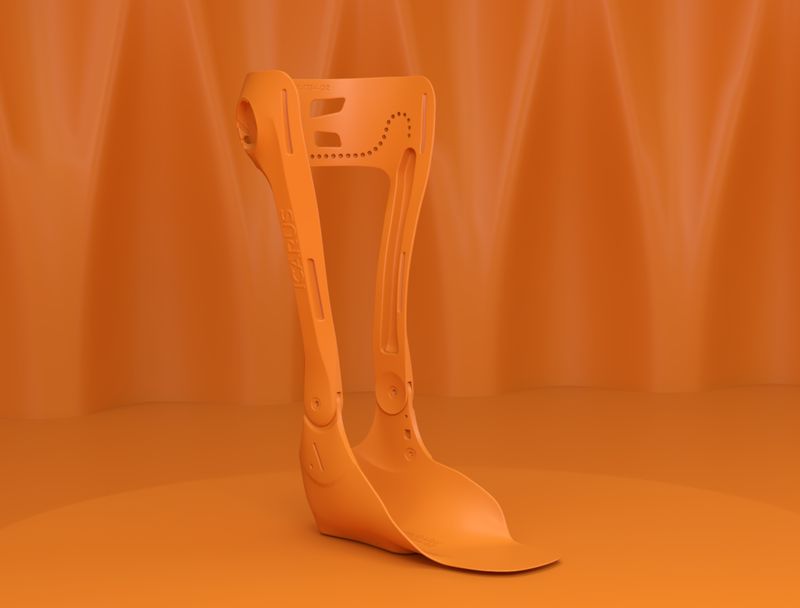
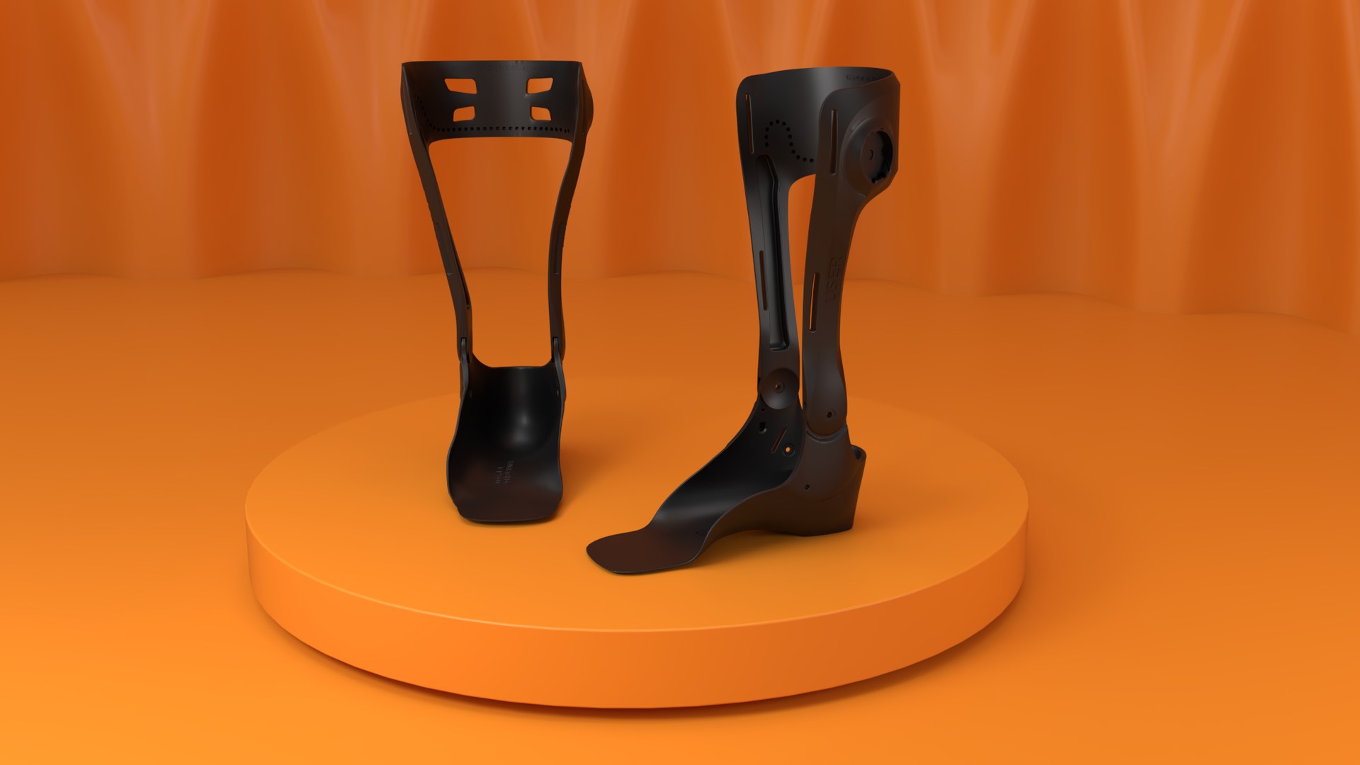
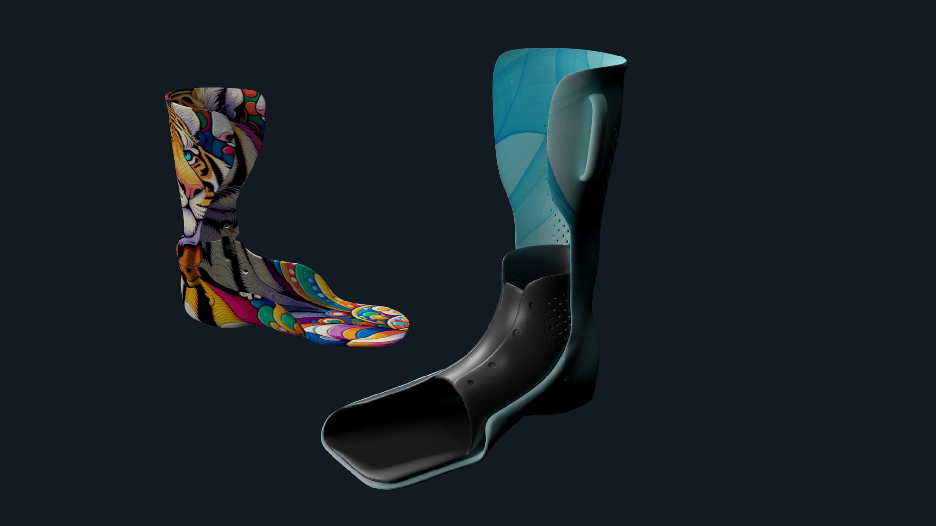
01 / HERMES & ZEUS Hermes & Zeus — articulated dynamic AFO, studio render

Hermes & Zeus

An articulated dynamic ankle-foot orthosis built as a system, not a model: one Grasshopper definition takes a leg scan and returns a print-ready, assembled device — shank, footplate, hinges and straps included.

Parametric System Scan-to-Production C# / RhinoCommon Mesh Processing Hinge Mechanism Web Configurator
In production

The Problem

Every patient gets a different scan, but the device still has to assemble: hinge axes must land on the anatomical joint, the footplate must meet the shank, the straps must clear both. Hand-modelling each one does not scale past a handful of patients.

The Approach

Anatomical landmarks are extracted from the mesh, the base geometry is segmented, remeshed and offset to wall thickness, and every module then rebuilds itself against those references. Where stock components stopped, I wrote custom C# ones — and the whole definition ships as a configurator the team runs without opening Rhino.

How it was built

Automated workflow — Grasshopper + ShapeDiver 100%
No hand-modelling in the loop: a new scan goes in, a valid device comes out.

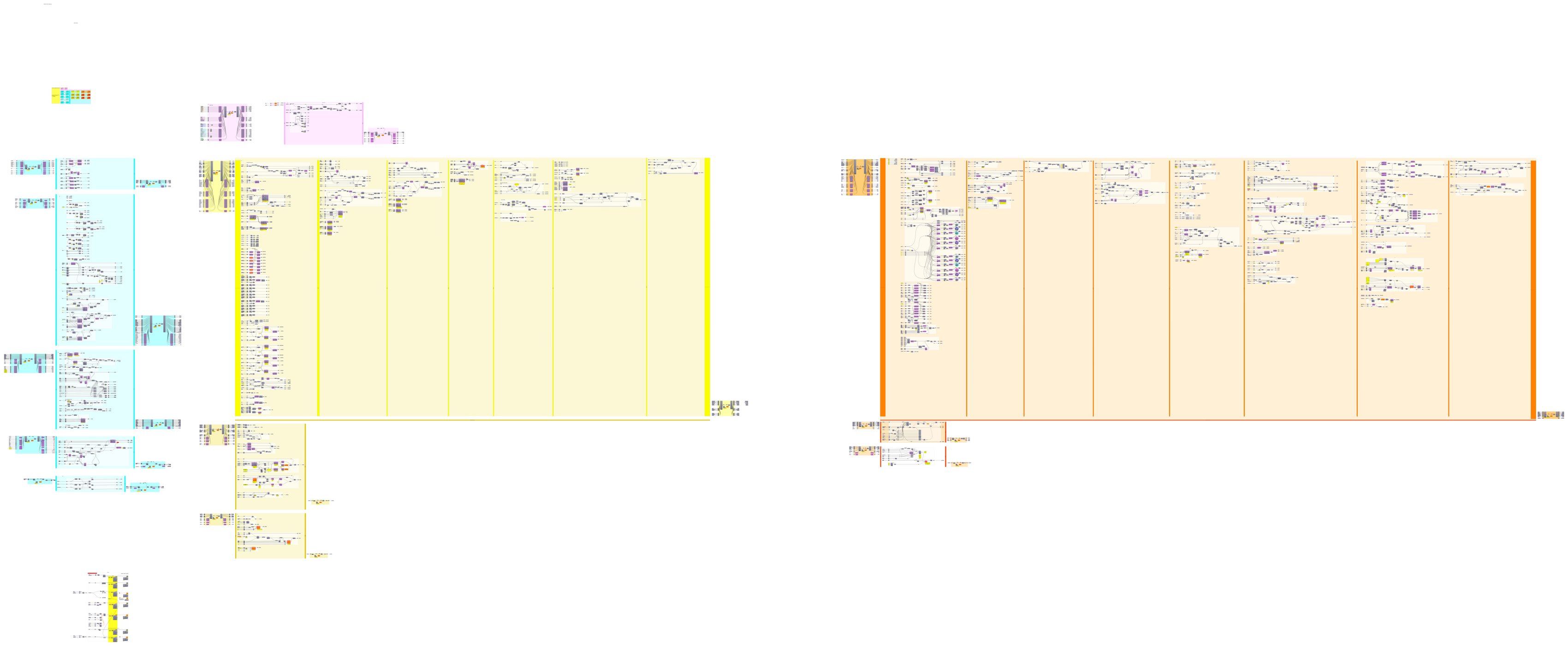
The definition

Grasshopper canvas — full Hermes & Zeus definition
↑ click to zoom — three macro-groups, left to right: landmark extraction & base-mesh preparation, footplate & thickness modules, rivet / anchor positioning.
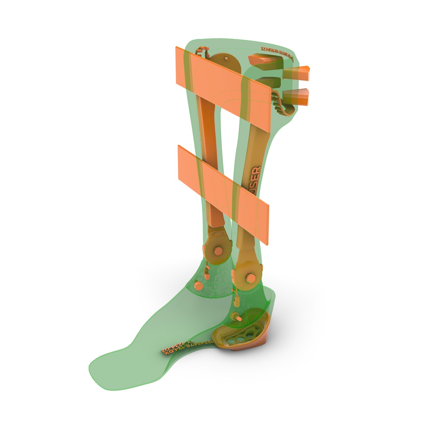
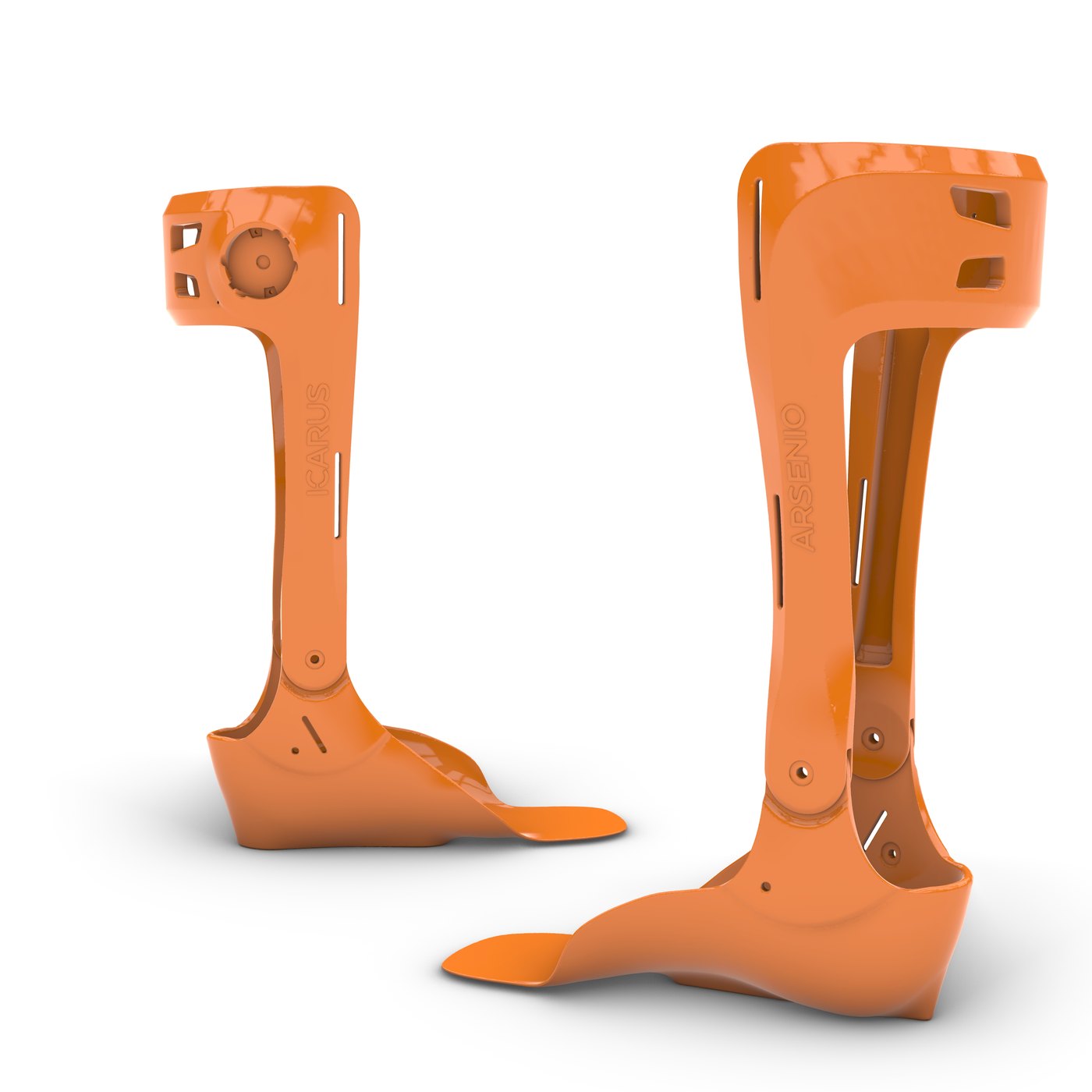
Assembled device — shank, footplate, hinges and straps
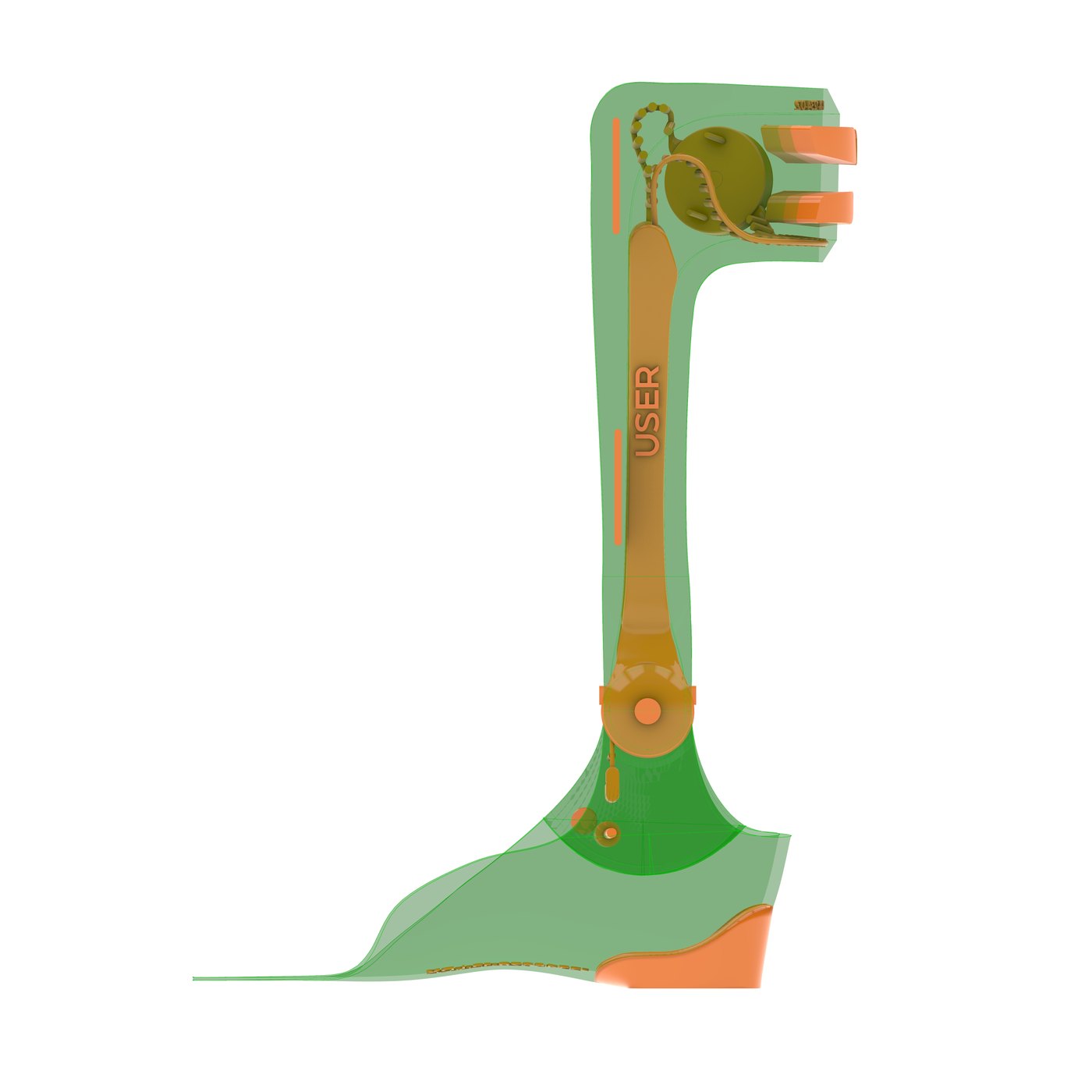
Side elevation — hinge axis aligned to the anatomical joint
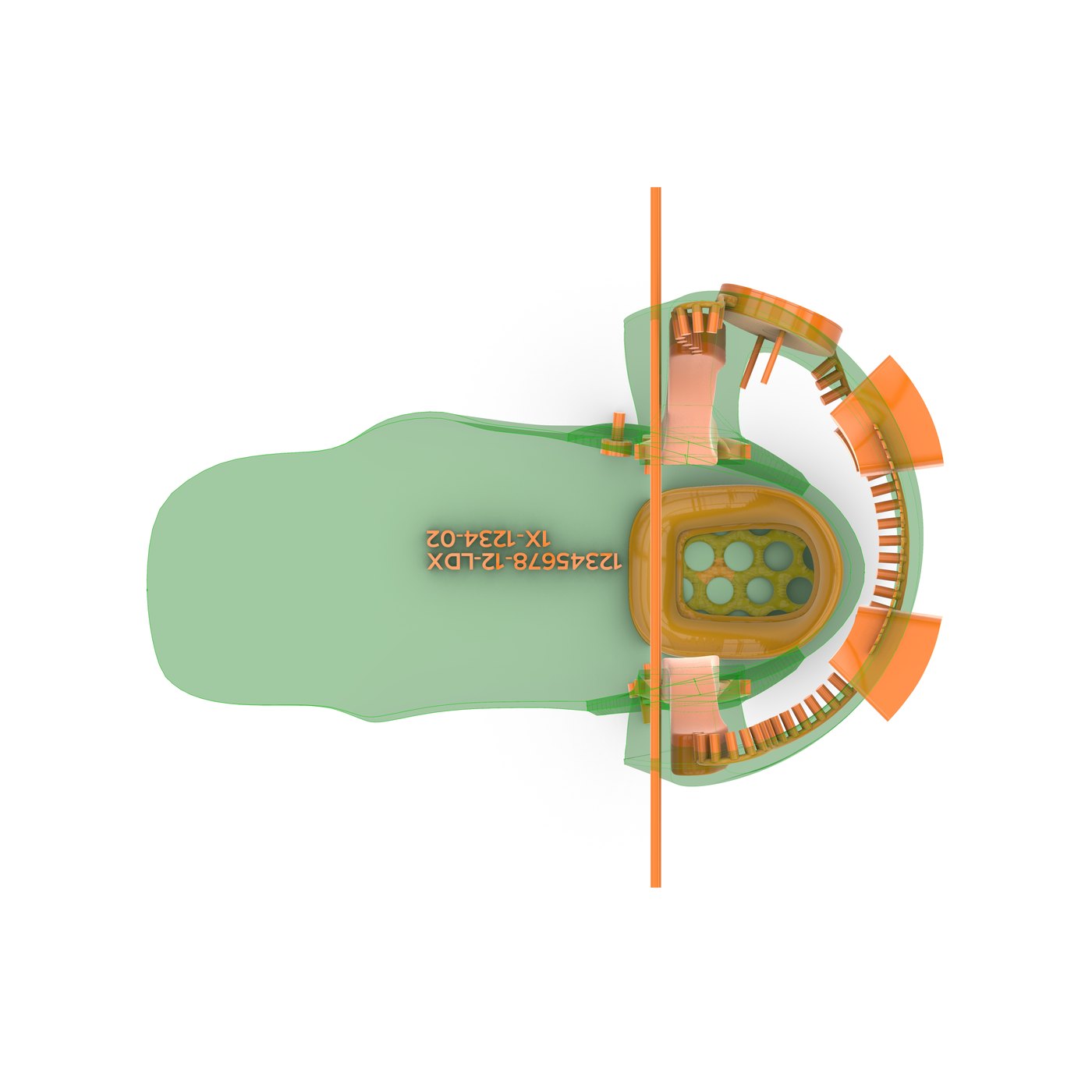
Footplate plan — radial hinge indexing
Printed parts, separated for fabrication
Technical views straight out of the definition — the assembly, the hinge indexing and the parts as they go to the printer.

Technical Highlights

Input
3D leg scan (mesh)
Toolchain
Rhino 8 / Grasshopper
Custom components
C# — RhinoCommon
Geometry pipeline
Landmarks → segments → quad remesh → features population → final device
Delivery
ShapeDiver web configurator
Output
Print-ready parts + assembly
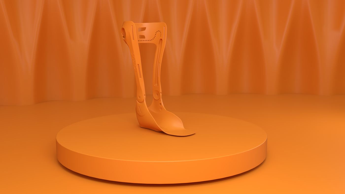
Hermes & Zeus — studio render, single device
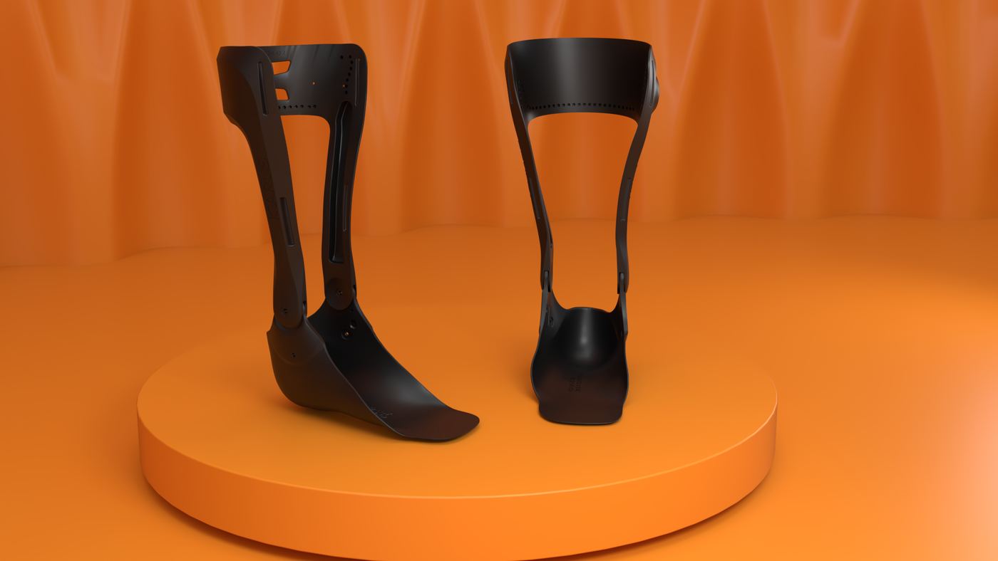
Hermes & Zeus — studio render, pair
Why it matters here — this is the part I care about: not automating a drawing, but building a system that survives contact with real production data and keeps producing valid, manufacturable geometry on inputs nobody has seen yet.

02 / AFO Patient-specific ankle-foot orthoses

Pediatric AFO

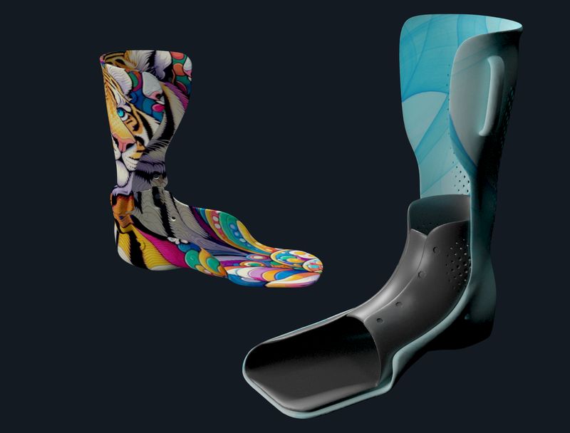
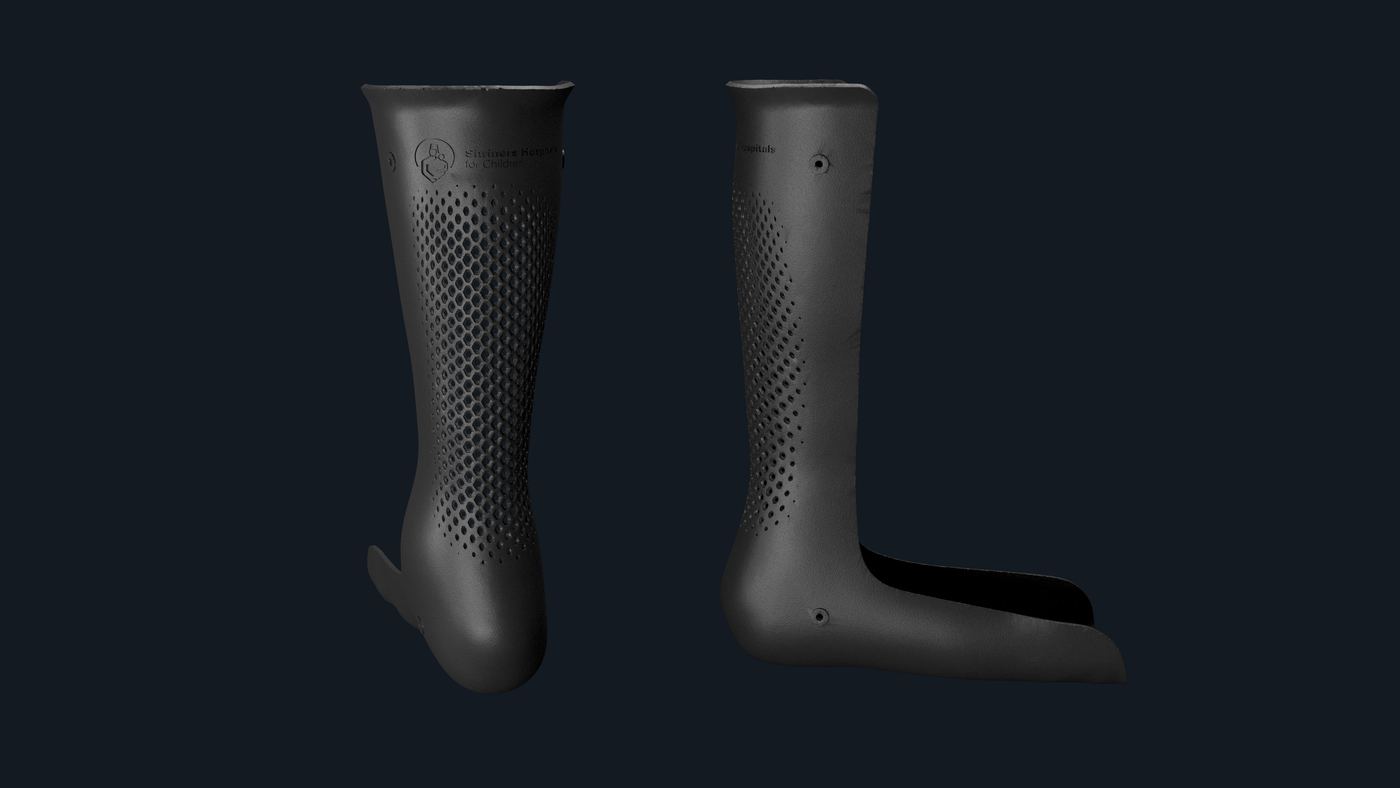
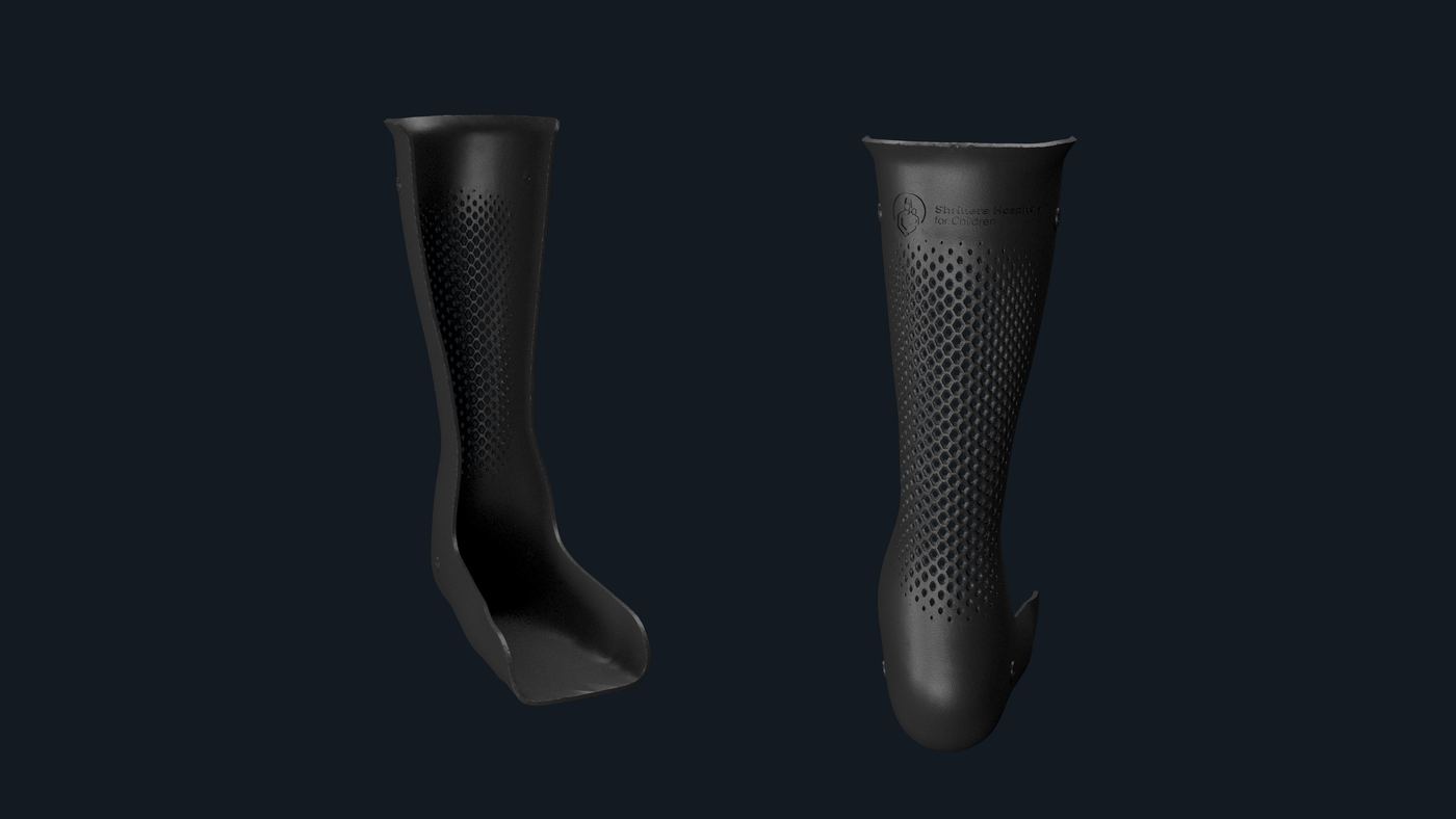
A family of ankle-foot orthoses generated from the patient scan — rigid shell, hinged variant and a perforated night splint — where fit, stiffness and appearance are parameters of the same model.

Ankle-Foot Orthosis Scan-to-Device UV Texture Mapping Lattice / Perforation Additive Manufacturing Mass Customisation
Product family

The Problem

An AFO supports the ankle through the gait cycle — but it is also worn all day, in public, often by children. Devices that fit badly or look clinical get left in the wardrobe, and a device nobody wears treats nobody.

The Approach

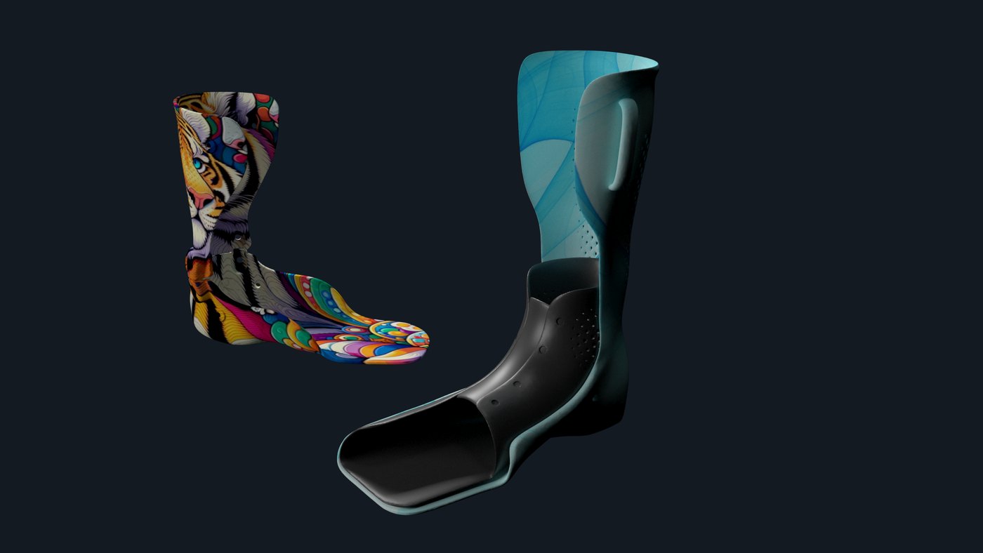
The shell rebuilds itself on each scan, and its outer surface then doubles as a design canvas: graphics are UV-mapped onto the double-curved shell without distortion, and openings are placed where stiffness allows. Same geometry, same clinical function, a device the patient picks.

How it was built

Automated workflow — Grasshopper 40% Manual modelling 60%
The shell and its graphics are modelled by hand; fit, trim lines and patterning are generated.

Variants

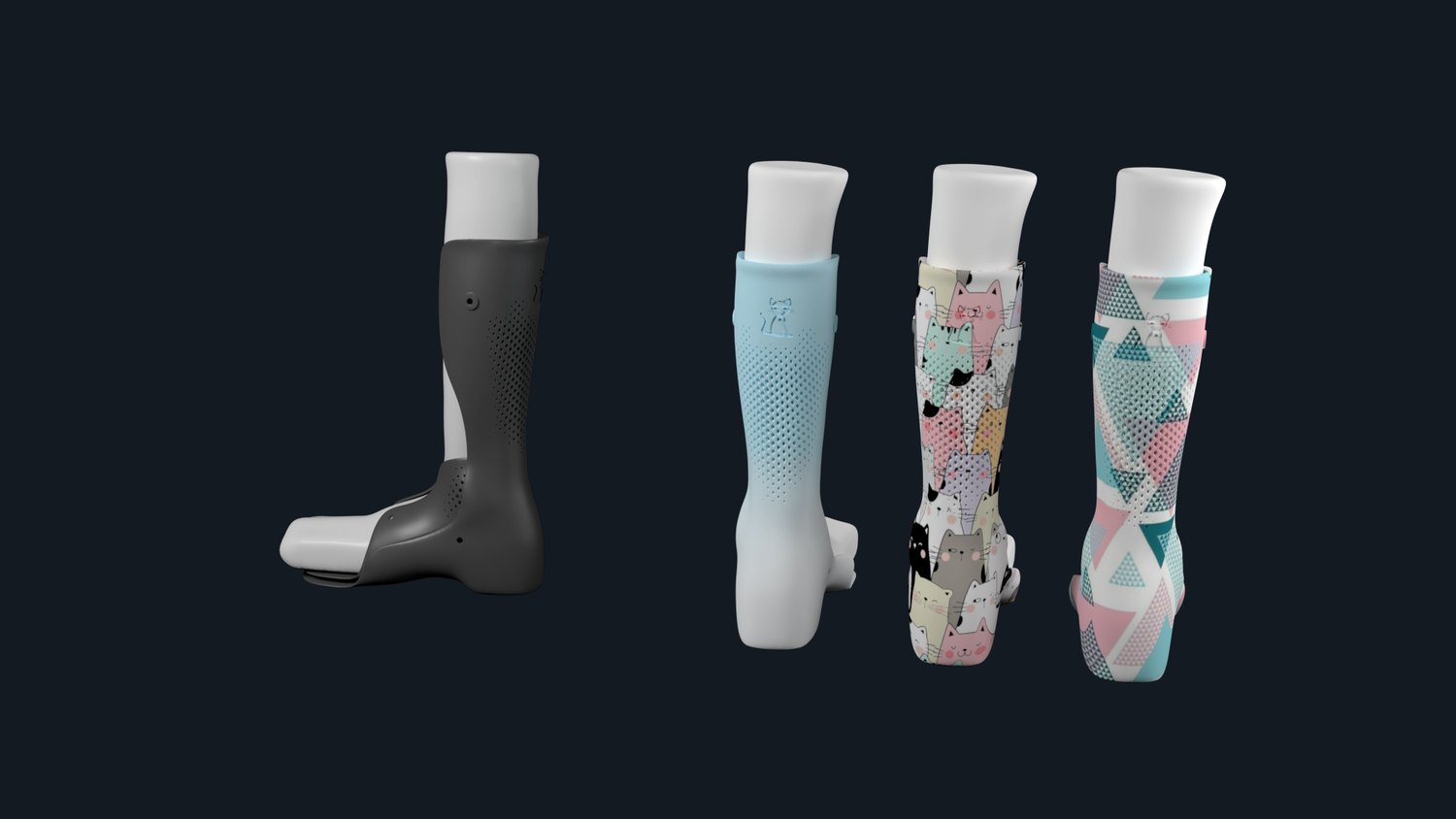
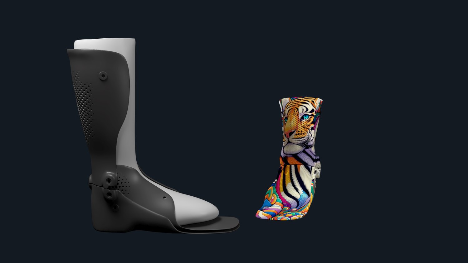
Rigid AFO shell — colourway variants
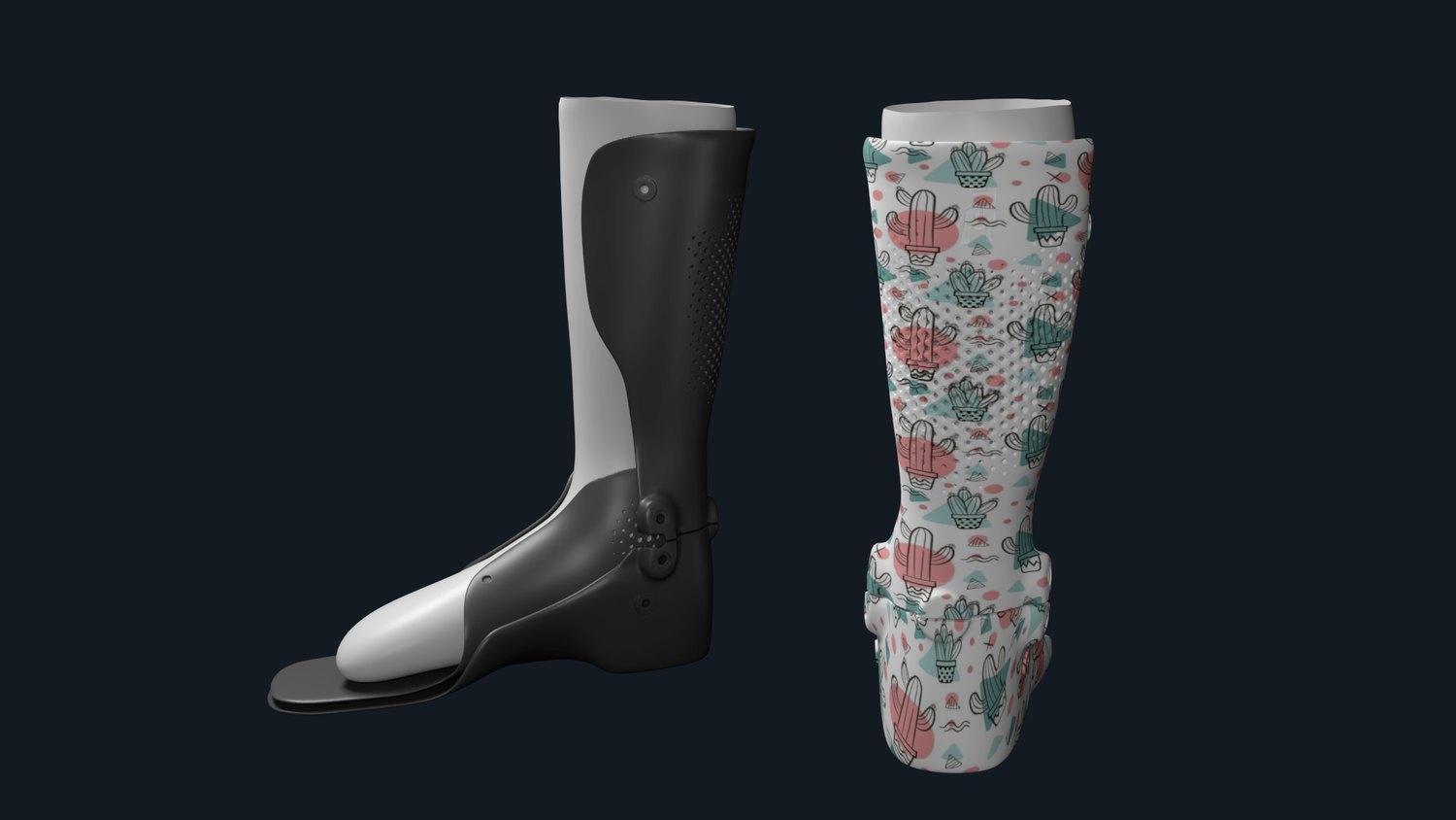
AFO with anterior shell
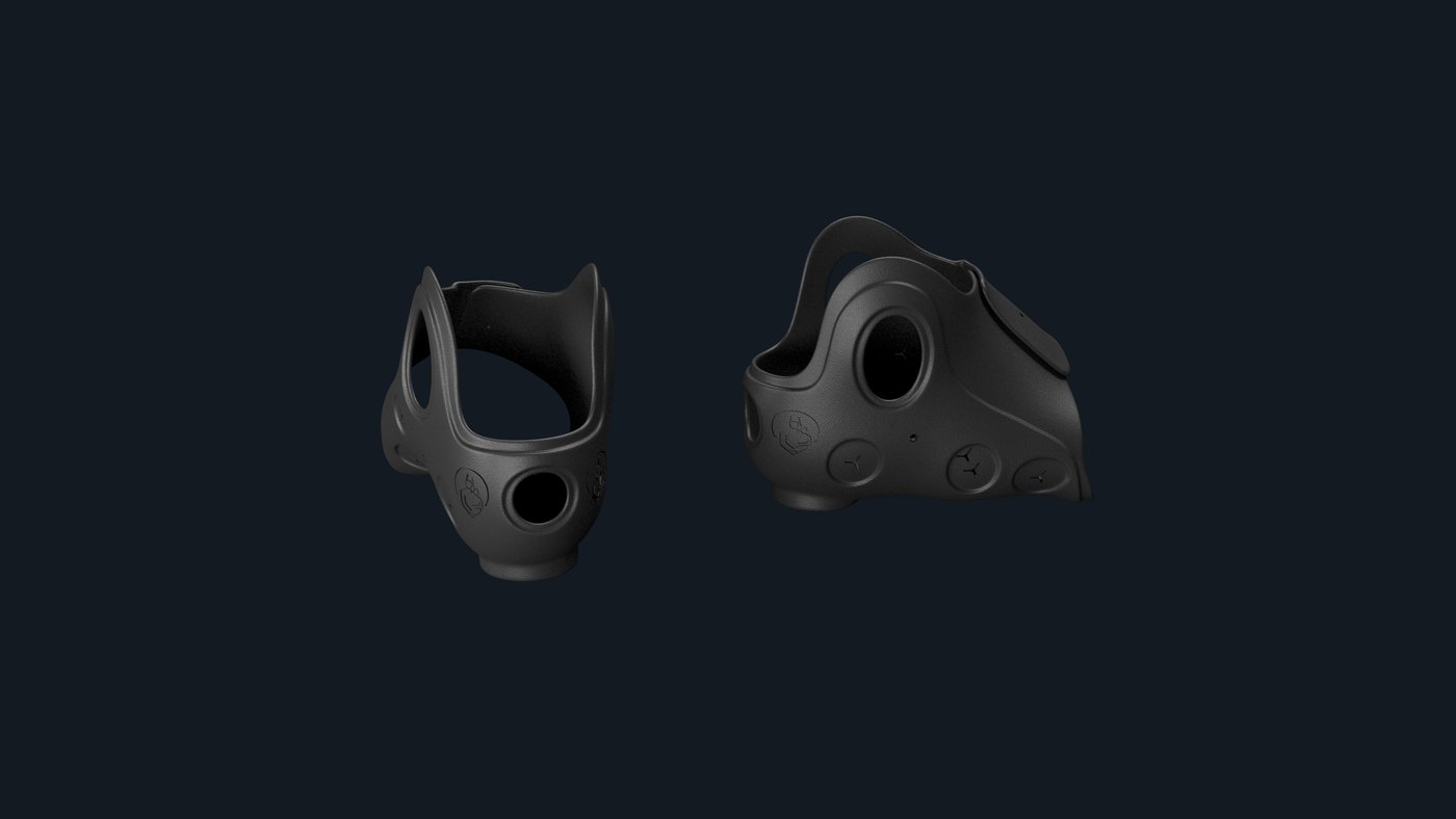
Shell pair — plain and patterned
Night splint — perforated lattice shell
Rigid shell · anterior-panel variant · night splint — worn overnight to hold the ankle in neutral dorsiflexion, perforated to stay breathable and light.
Texture application

Raster graphic mapped onto the curved shell surface

Flat artwork → curved shell

The shell is unrolled to a flat parameter space, the artwork is laid out on it, and the result is mapped back onto the double-curved surface. The print stays continuous across the curvature — no seams, no stretch at the ankle.

It is the same operation a knitted upper needs: a 2D pattern that has to land correctly on a 3D last.

Technical Highlights

Device
Ankle-Foot Orthosis (AFO)
Input
3D lower-leg scan
Variants
Rigid · anterior shell · night splint
Surface
UV-mapped graphics, per patient
Lightweighting
Perforation / lattice patterning
Design tool
Grasshopper / Rhino
Night splint — lattice detail
Two shell variants side by side
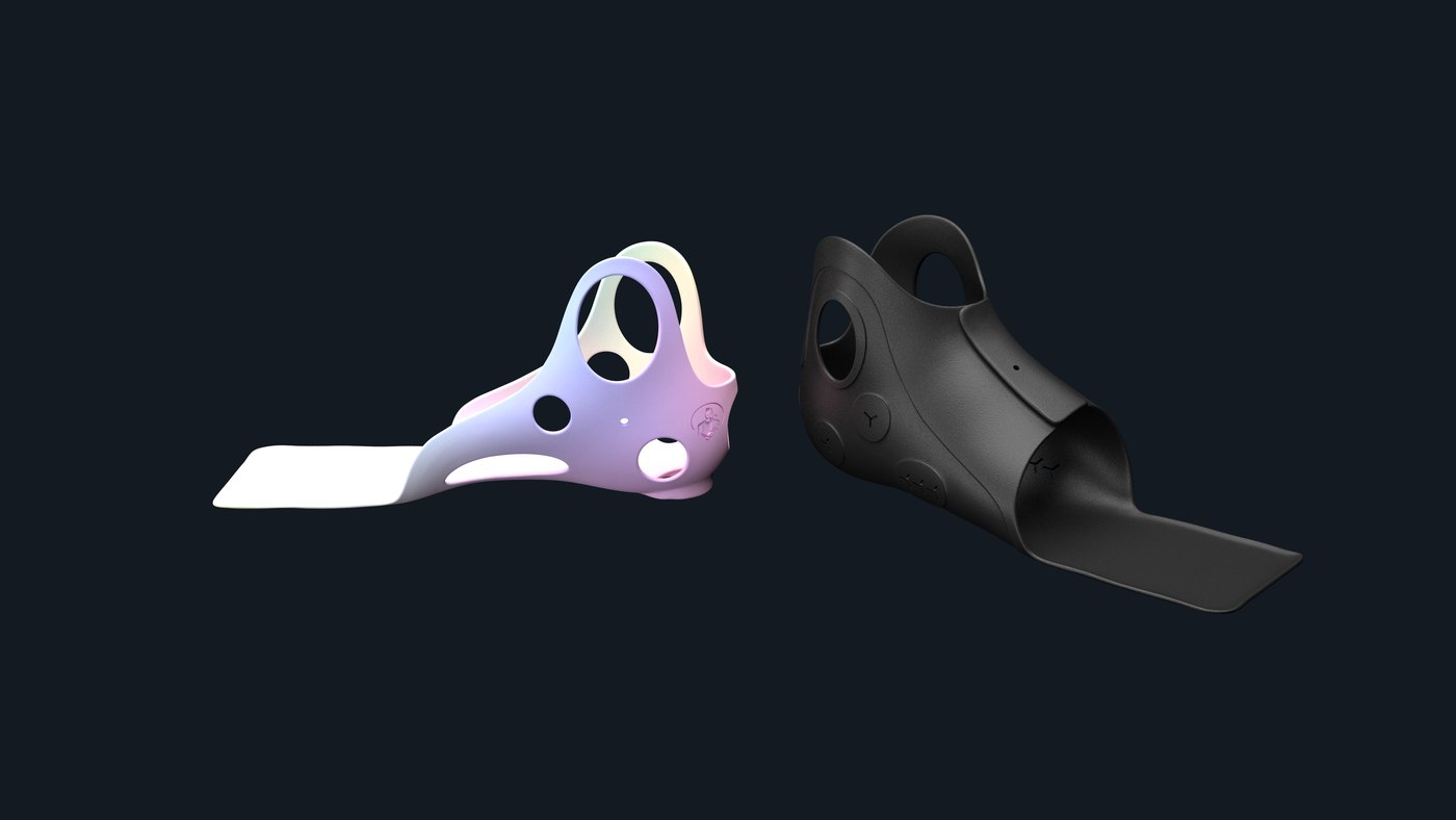
03 / SMO Supramalleolar orthoses

Supramalleolar Orthoses

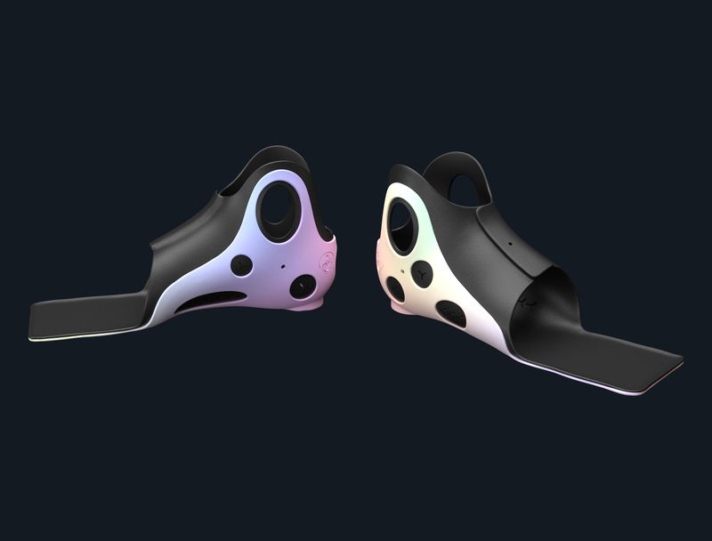
A low-profile shell that controls the hindfoot while leaving the ankle free — the smallest device that still does the job, generated per patient.

SMO Paediatric Foot & Ankle Geometry Trim-Line Control 3D Printed Parametric Fit
Product family

The Problem

Children with flexible flatfoot or low muscle tone need frontal-plane control of the hindfoot — but a full AFO blocks the ankle they still need to develop. Too much device is its own failure mode.

The Approach

The shell wraps just above the malleoli and stops there. Trim lines, window openings and wall thickness are sliders on a scan-driven model, so a clinician's adjustment is a parameter change — not a remodel.

How it was built

Automated workflow — Grasshopper 80% Manual modelling — Rhino SubD 20%
Mostly generated; the organic shell transitions are refined by hand in SubD.

Research & iteration

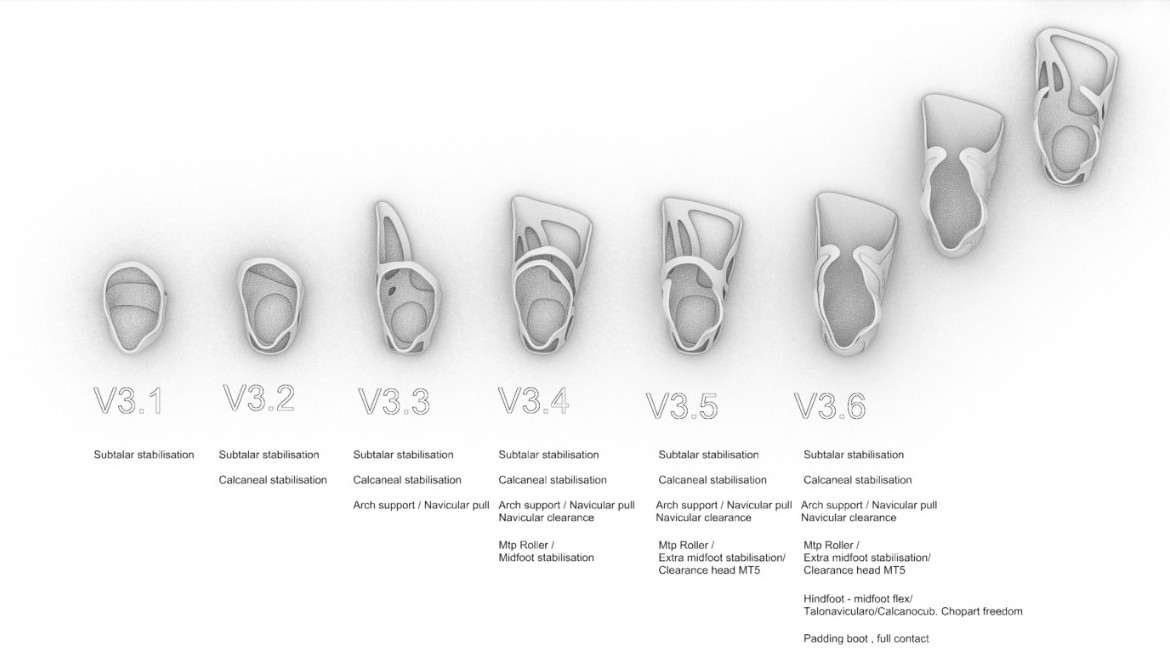
SMO design iterations, V3.1 to V3.6
↑ click to zoom — six generations, each adding exactly one control: subtalar stabilisation, then calcaneal, arch support with navicular pull and clearance, MTP roller and midfoot stabilisation, MT5 head clearance, and finally hindfoot-to-midfoot flex — talonavicular / calcaneocuboid, Chopart freedom — with a full-contact padding boot. Nothing was added that could not be justified biomechanically.
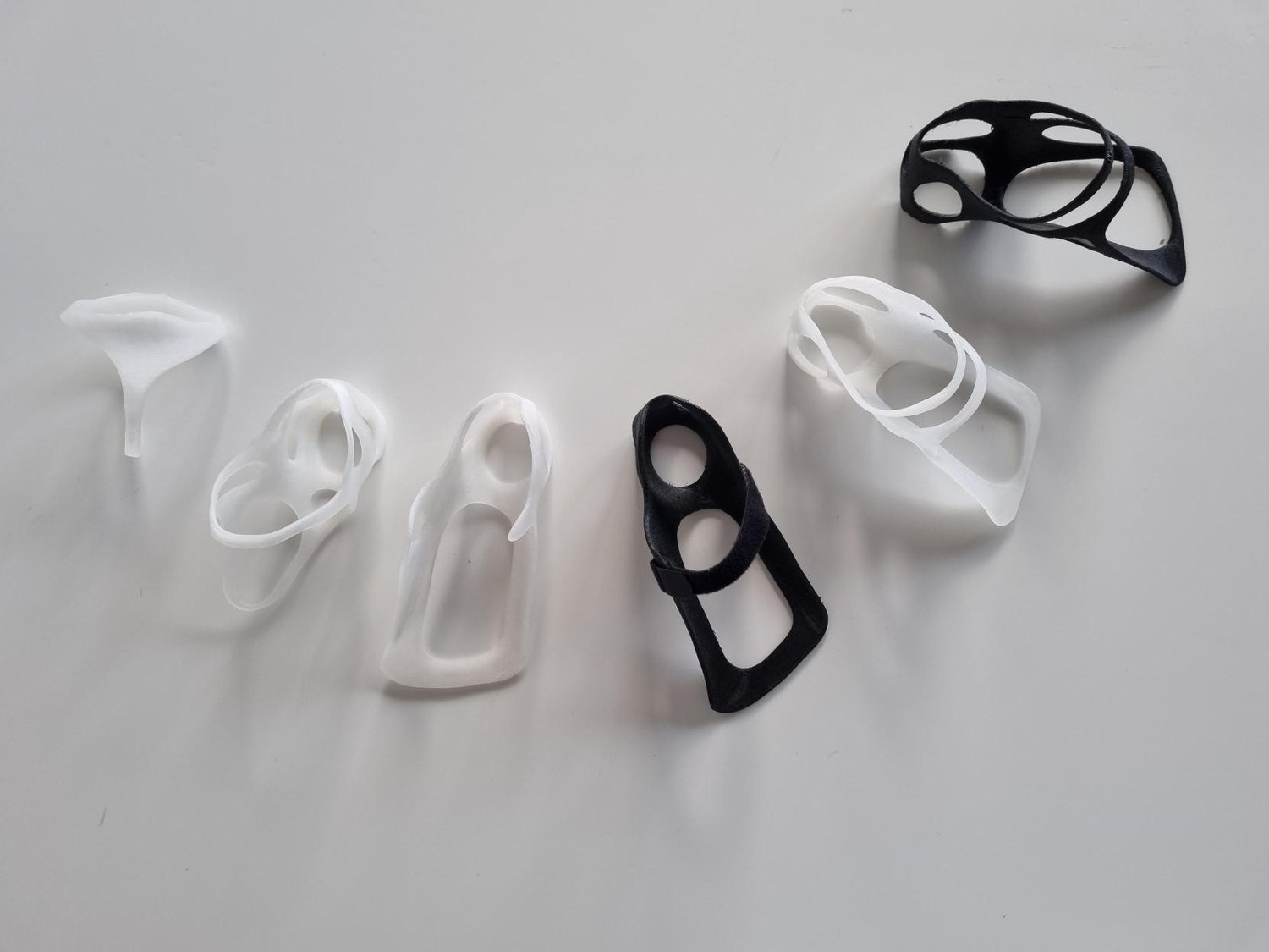
Printed SMO prototype shells
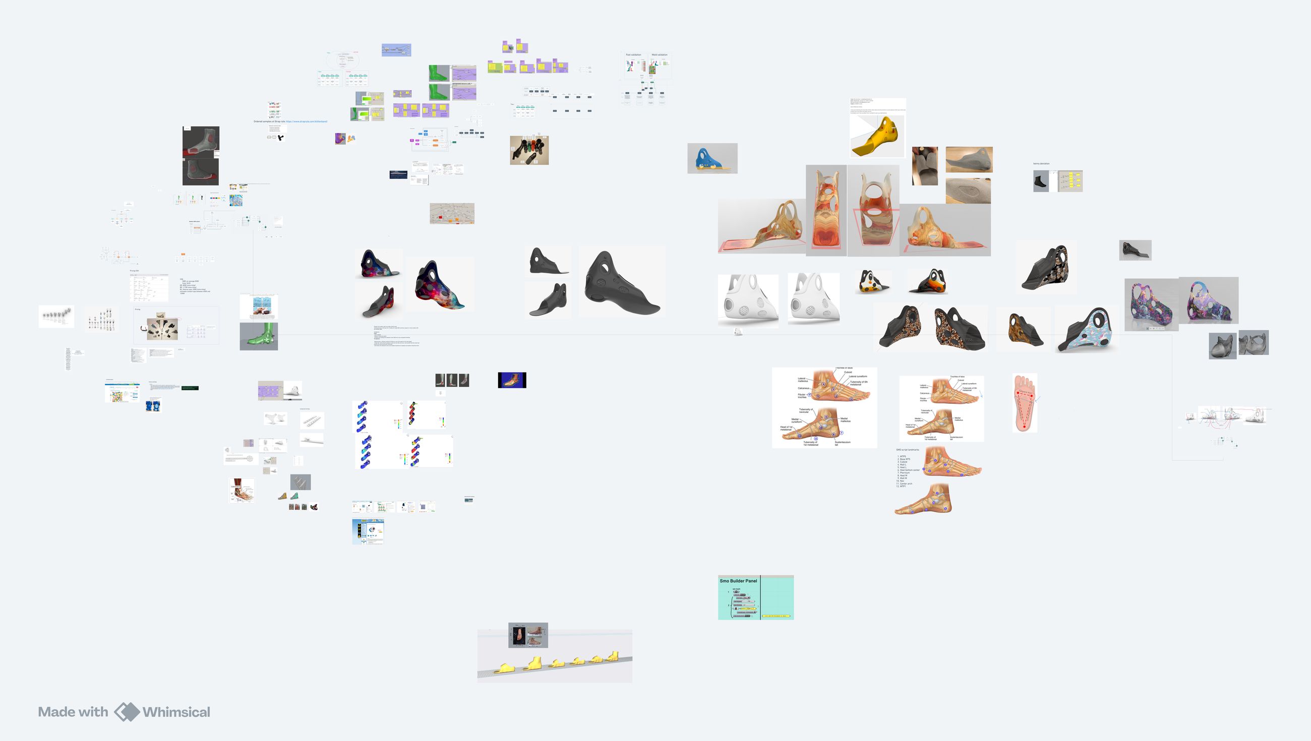
Research board — footwear, last and gait references
Printed test shells · the research board behind the form — footwear, lasts and gait references.
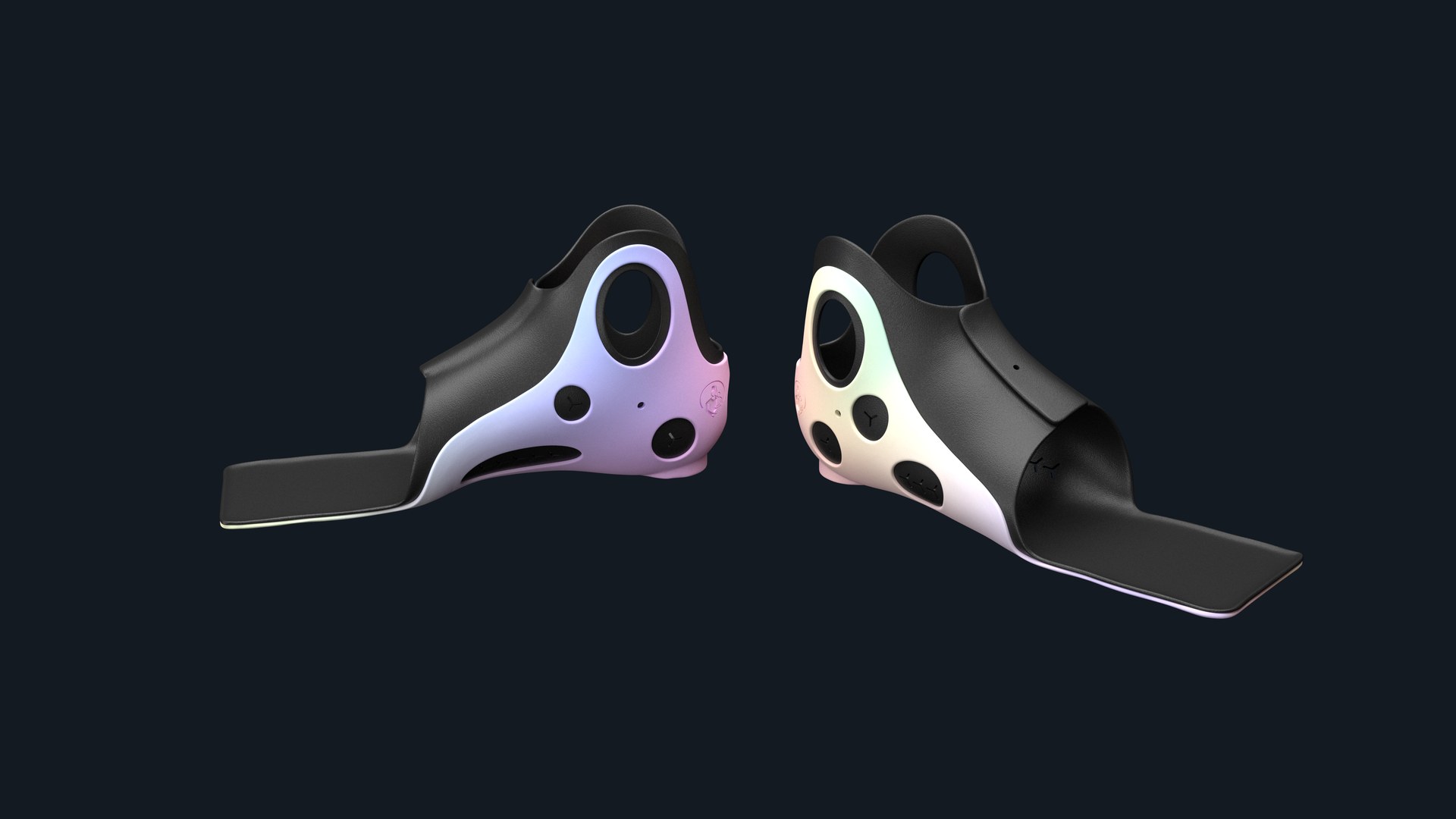
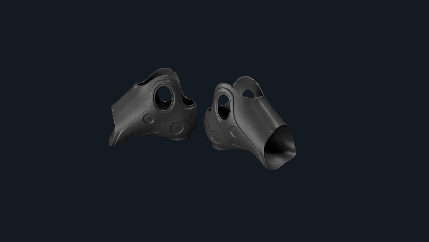
Supramalleolar orthosis — pair
Extended footplate variant
Shorter shell variant
Window openings and trim lines
Extended footplate · short shell — same model, different parameters.

Technical Highlights

Device
Supramalleolar Orthosis (SMO)
Control
Subtalar, frontal plane
Input
3D foot & ankle scan
Trim height
Just above the malleoli
Parameters
Trim lines · windows · wall thickness
Design tool
Grasshopper / Rhino
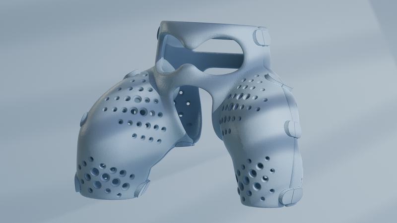
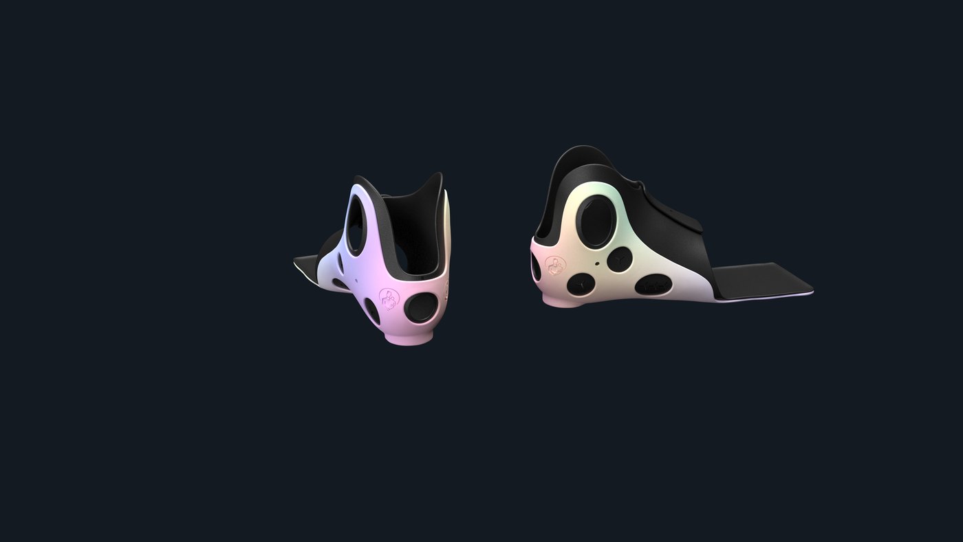
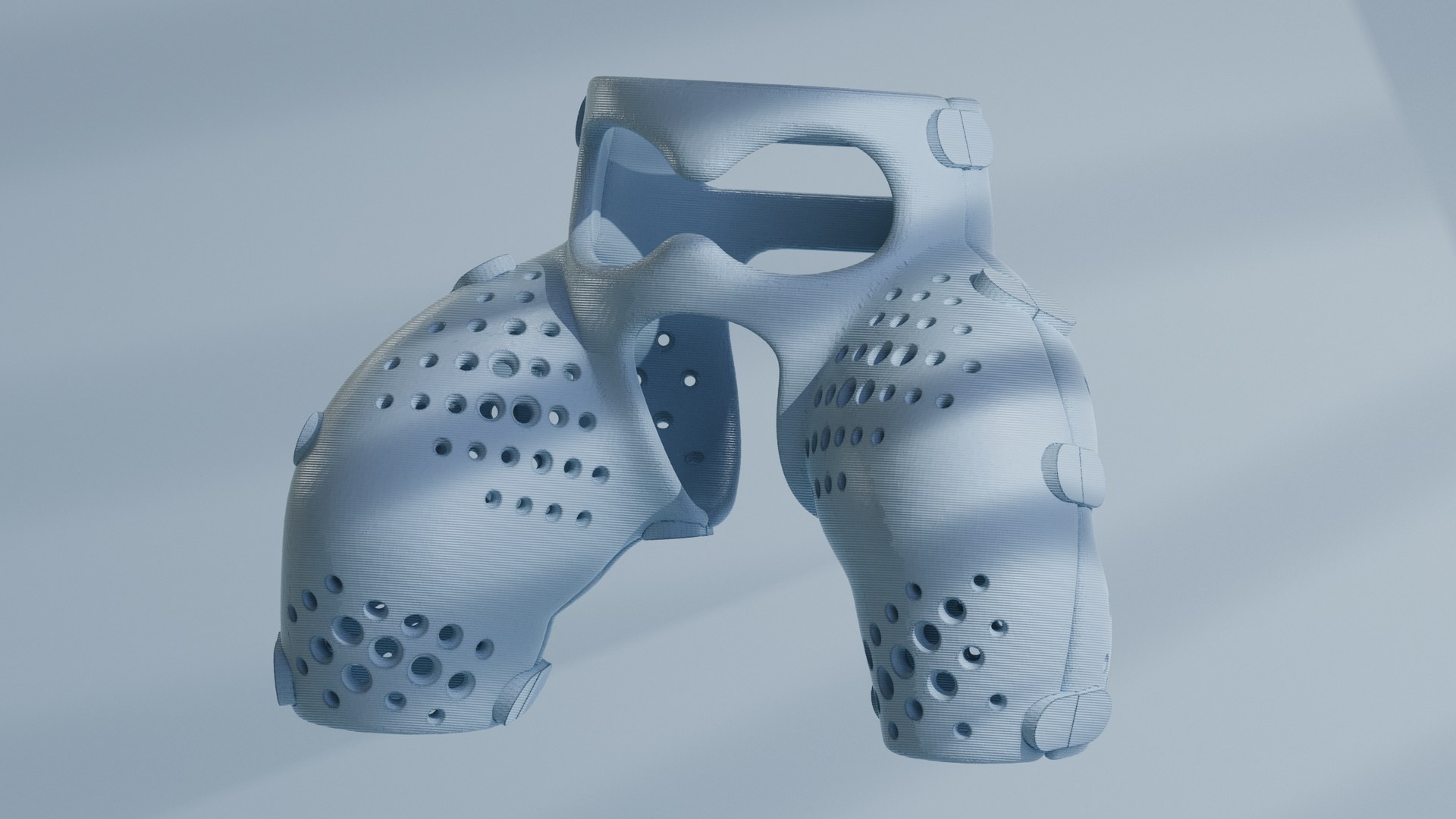
04 / HIPCARE Hipcare orthosis — studio render

Hipcare

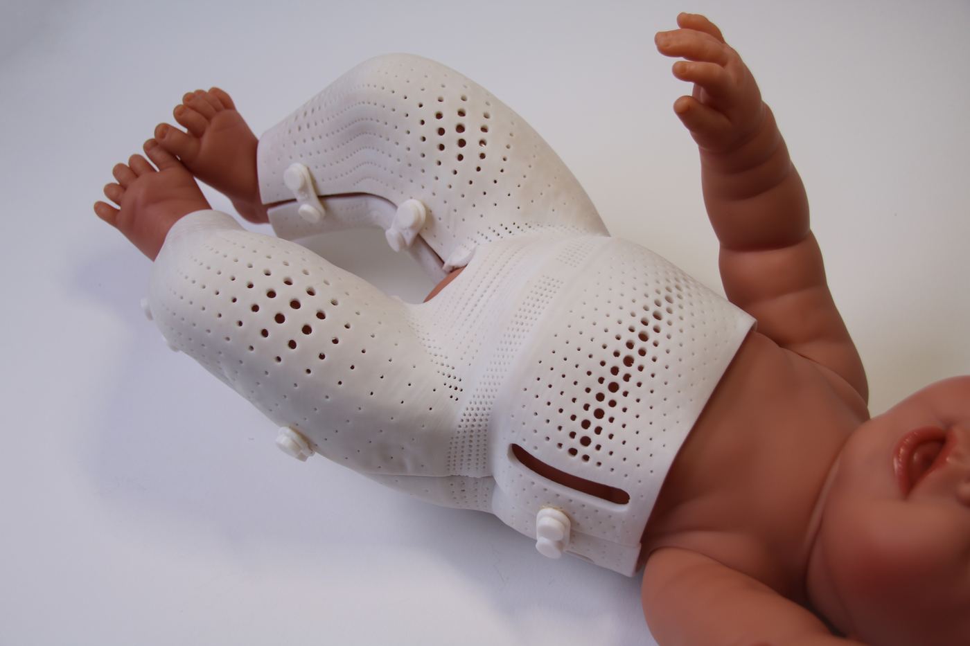
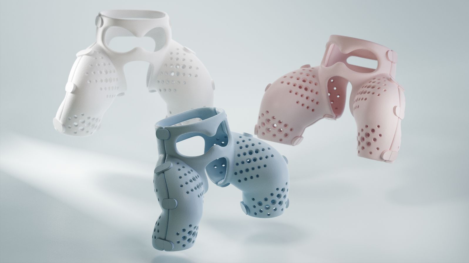
Patient-specific 3D-printed orthosis for infants with hip dysplasia (DDH) — a lightweight, parametric alternative to the traditional plaster spica cast.

Paediatric Device Hip Dysplasia (DDH) 3D-Printed Orthosis PLA / Lattice Structures Parametric Design Digital Fabrication
Award-winning Prototype

The Problem

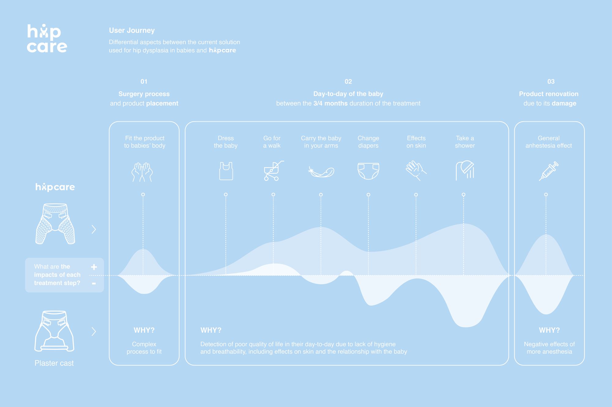
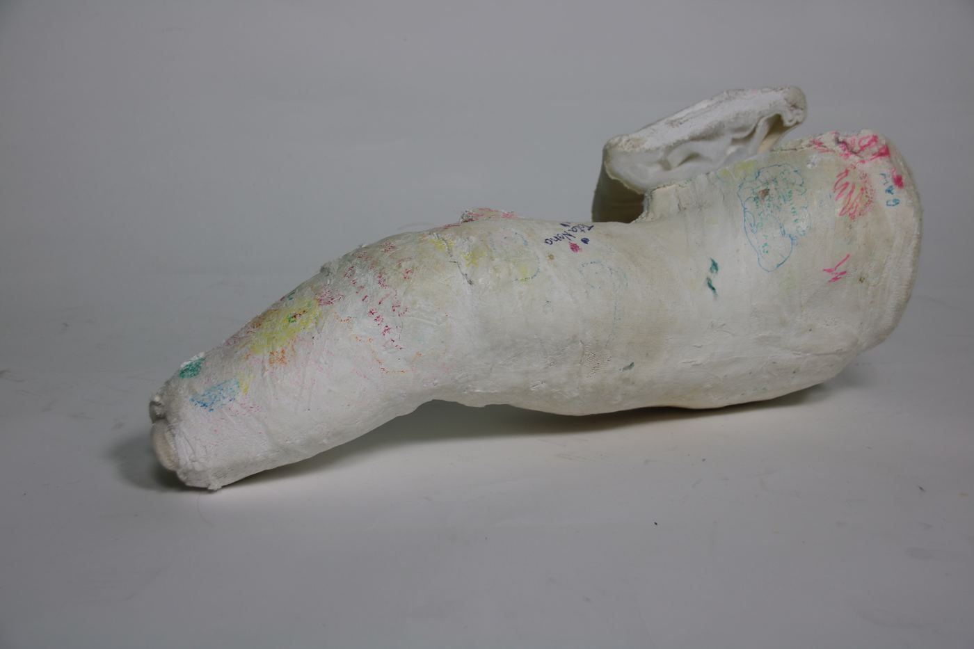
Developmental dysplasia of the hip (DDH) affects 1–3% of infants. Treatment requires 3–6 months of continuous immobilisation — currently achieved with heavy plaster spica casts that are painful to fit, prevent diaper changes, and cannot be adjusted as the baby grows.

The Solution

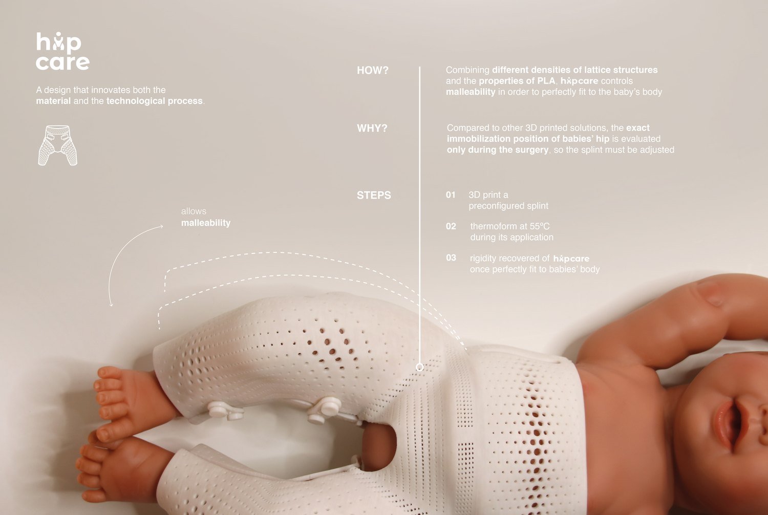
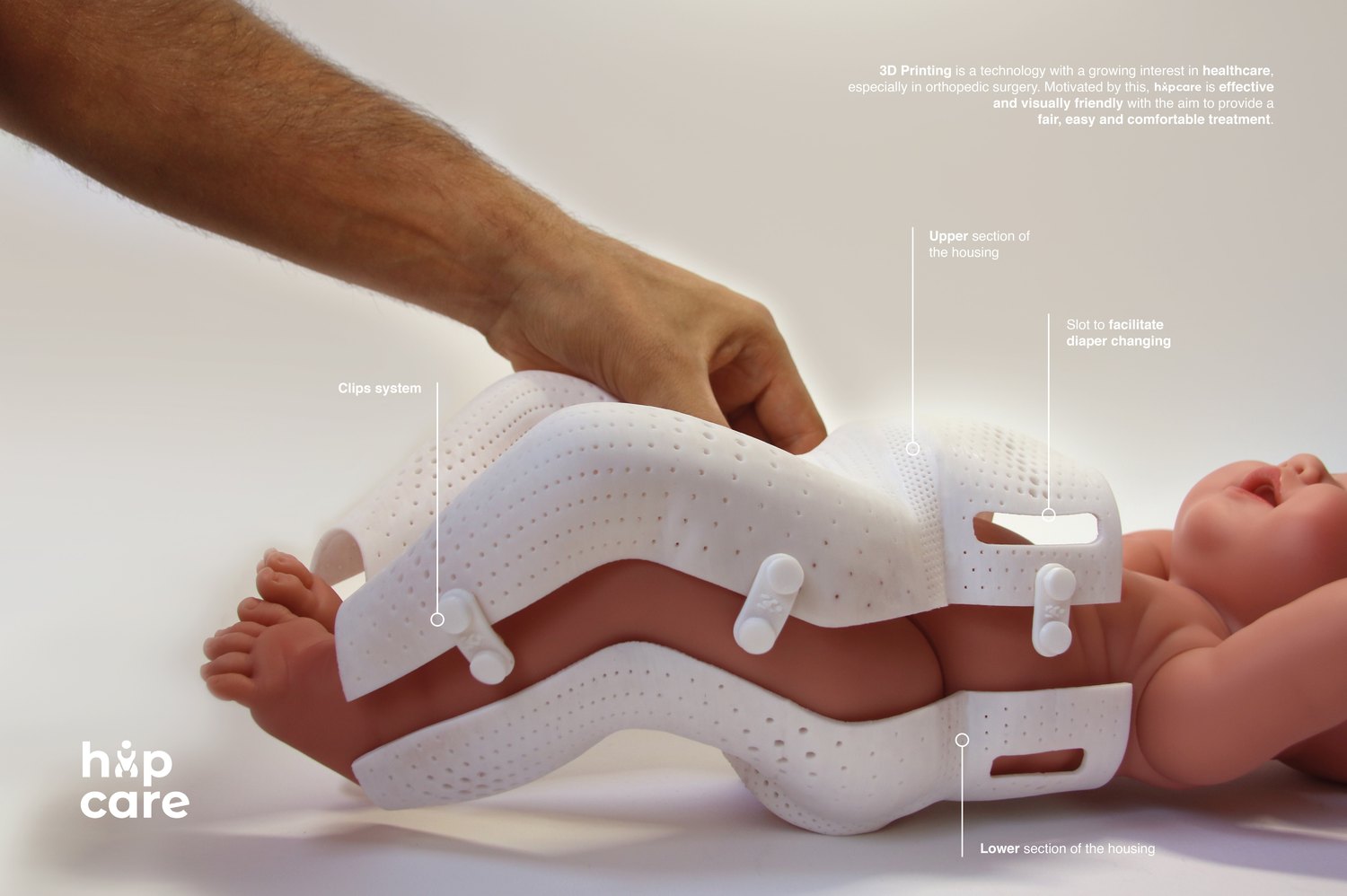
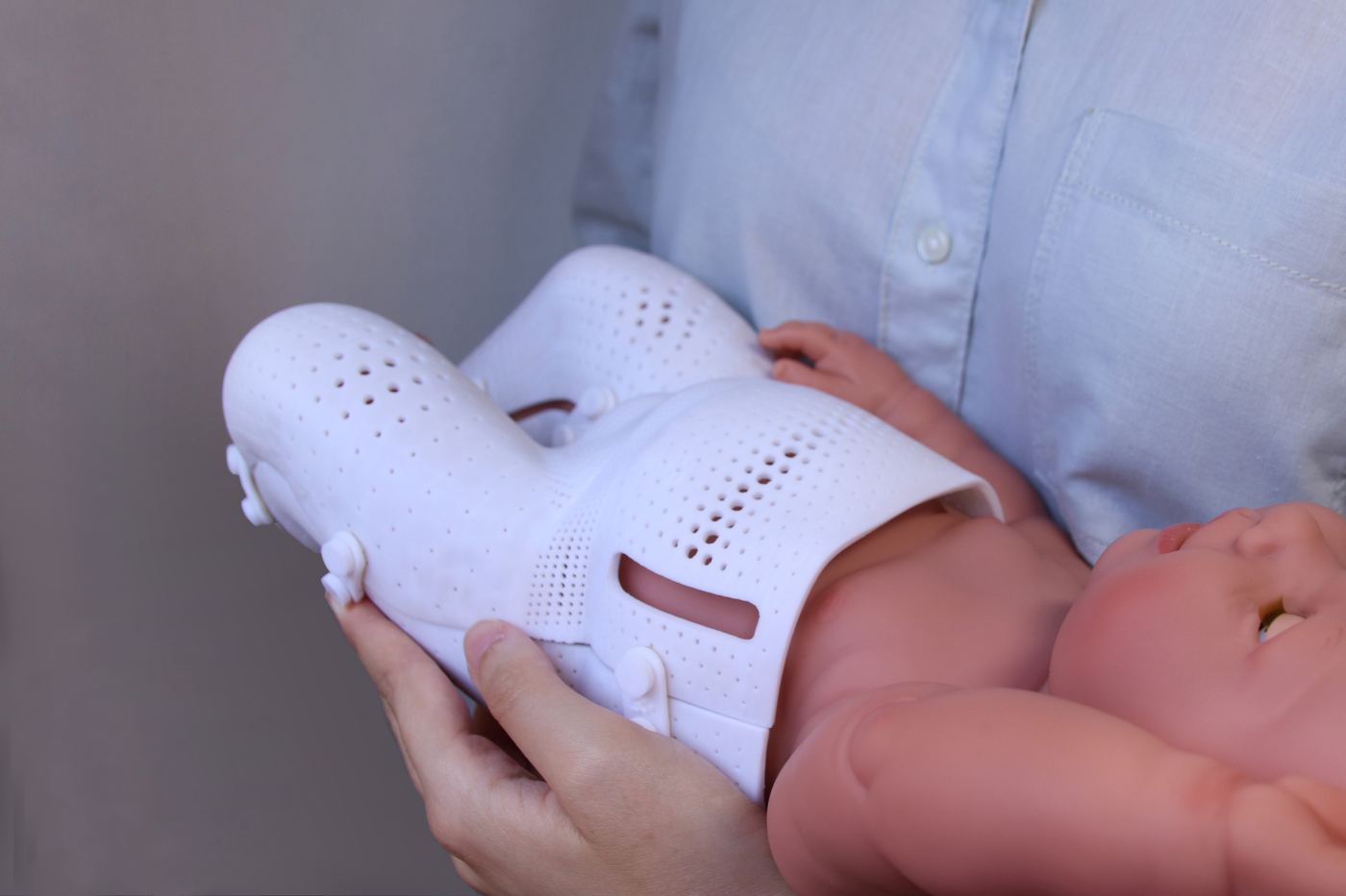
Hipcare is a parametrically designed, patient-specific PLA orthosis with variable-density lattice structures. It is 3D-printed per patient, softened at 50 °C for a precise fit, and features a clip system that allows diaper changes — all without removing the device.

How it was built

Automated — lattice pattern in Grasshopper 10% Manual modelling — Maya 90%
A student project, modelled by hand — the automation is the lattice. Six years later, project 01 is the inverse.
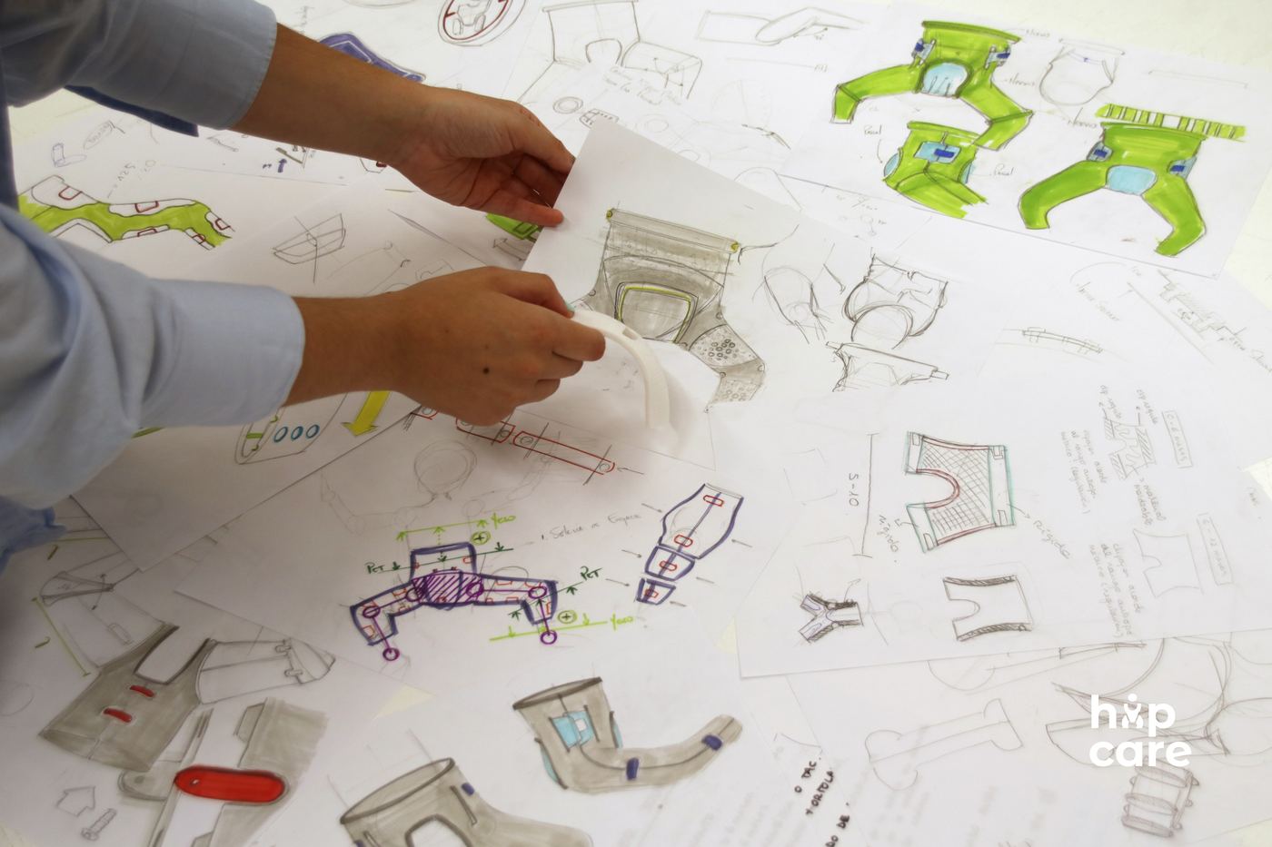
Hipcare design sketches
Hipcare — how it works
Hipcare — device detail and annotations
Hipcare prototype on infant model
Hipcare prototype — held by clinician
Hipcare user journey — vs spica cast

Technical Highlights

Material
PLA (biocompatible)
Fabrication
FDM 3D Printing
Compliance ref.
ISO 10993
Structure
Variable-density lattice
Fitting method
Thermoplastic at 50 °C
Design tool
Grasshopper / Rhino

What it replaces

Traditional plaster spica cast

Traditional Spica Cast

  • Heavy plaster — worn 3–6 months continuously
  • Fitted under anaesthesia; cannot be adjusted as baby grows
  • Prevents normal diaper changes and bathing
  • No visual or tactile feedback on skin condition underneath
Hipcare replaces all of this with a single 3D-printed, patient-specific orthosis.
Hipcare — white, blue and pink colourways
🏆
European Product Design Award 2024 — 1st Place
Medical Category — Hipcare paediatric hip dysplasia orthosis

Capabilities

Tools & Expertise


Four years of parametric design and digital fabrication, on top of a materials engineering degree — and the programming to push past what the stock nodes do. I write the components I need, and increasingly I build with AI models in the loop.

Parametric & Computational Design

Rhinoceros 3D — 4 yrs Grasshopper — 4 yrs Computational geometry Design automation Mass customisation

Programming

Python C# / .NET RhinoCommon API Custom GH components REST APIs / FastAPI Git

AI & Agentic Workflows

AI-assisted development LLM tooling & agents Claude Code MCP integrations Prompt engineering

Geometry & Scan Data

Scan-to-CAD Mesh processing / remeshing Anatomical landmarking Lattice & pattern generation UV / conformal mapping Reverse engineering

Simulation & Optimisation

FEA / structural analysis Topology optimisation Simulation-driven design Material selection (CES / Granta)

Deployment

ShapeDiver — 2 yrs Web configurators Cloud parametric apps

CAD / 3D Modelling

SolidWorks PTC Creo Autodesk Inventor Maya Blender

Rendering & Visualisation

V-Ray KeyShot Technical visualisation

Digital Fabrication

FDM / FFF Printing SLA / Resin Laser Cutting Robotic Arm (ABB, KUKA) DfAM

Materials & Compliance

Biocompatible materials ISO 10993 ISO 13485 MDR Materials & nanotechnology

Domain

Orthotics & prosthetics — 3 yrs Patient-specific devices Medical device development Product design

Languages

Italian — native English — C1 Spanish — C1 French — basic

Education

2023
Controlmad
Madrid

Master Course — Parametric Design & Digital Fabrication

  • 350 h · PanelingTools for Rhino certification
2022
ELISAVA — UPF
Barcelona

Master's Degree — Product Design & Development

2021
Politecnico di Milano
Milan

Bachelor's Degree — Materials & Nanotechnology Engineering